Audacius Keypad
So, as we told you before, to be a true audacius robot-maker, you will have to mount and solder your own keypad. We will explain how to do it as detailed as possible, assuming no familiarity with this kind of things. If you have some basic electronics and soldering skills, we guess that taking a look at the schematics will be enough for you.
So... let's get started!
Is it the first time you will solder?
Even if you have never soldered before, this is not so difficult. It is just putting a drop of solder in each hole that a component is placed, making sure they get a electrical connection with the board and that they also get a mechanical connection that avoids them from falling. We recommend you to take a look at this fantastic comic, it will take you 15 minutes and you will know everything you need to know.
Check stuff
This is what you should have in your desk to start with the keypad:
| Component | Quantity |
|---|---|
| 18X17 lines Stripboard | 1 |
| 6x6 mm SPST-NO tact switch | 5 |
| 10KΩ Resistors (1/4 watt) | 6 |
| 1MΩ Resistors (1/4 watt) | 1 |
| 0.28 mm2 solid wire | 1 |
| 2.54 Right Angle connector (or any other header pin of your choice) | 1 |
| Male Header pins (optional) | 2 |
| Jumper Cap (optional) | 1 |
Cut the stripboard
You probably won't find a stripboard that is precisely the size we ask for. It's not a problem, you just have to cut it, and it's very easy!
We recommend you to see this video , put some gloves on, and proceed!
Cut the lines on a stripboard
With some sharp knife or xacto, you have to make two cuts on the lines of the stripboard. Very carefully, you have to strip off a bit of the copper on the places marked in red, so that there is no electric connection between the holes on the sides.

Drill holes
Take a drill with a 3 mm. bit and make four holes, exactly over the stripboard's holes that we mark in green.

Place components
The placement is fully explained on the wiki. Switches stay in place quite well, but resistors and wires tend to fall when you turn the board down, you should bend their terminals forming an angle so they don't sweep through the holes so easily.
This is the final placement of every component.
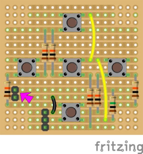
NOTE: Do you see the two black squares pointed with a pink arrow? Those are the two optional header pins that we told you. You only need to put them in case you want to work with 3-wire configuration on your keypad. Escornabot's firmware comes set by default to a two-wire keypad, so, if you are not sure what to do, just don't put this component.
Solder components
Well... you've read THE COMIC, haven't you? So, you know how to do it... Go! :)