Wire connections
It's very easy to wire your escornabot, you just need some (14-15) male-female jumpers and follow this simple steps.
Plug motors to drivers:
Easy! they only go in the proper way and then... well, left motor to left driver, right motor to right driver! Did you expect that?
Plug the arduino on the breadboard
Carefully or not, stick the arduino on the breadboard. Be sure to leave three empty rows of the breadboard on the same side as in the picture. From now on, you can reach any pin in the arduino just sticking the "male" side of the jumper on the same column as the pin. For example, that orange wire of the picture would connect whatever to arduino's D6 pin.
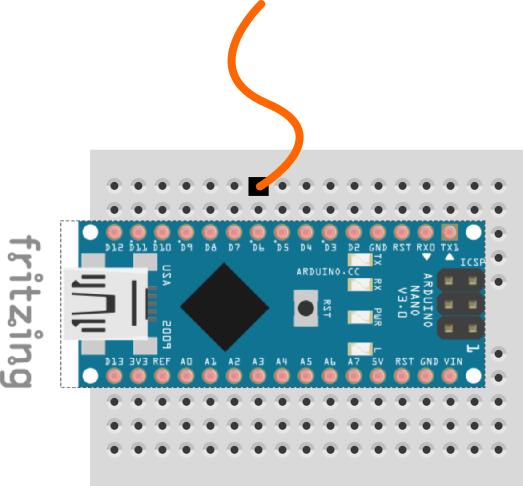
Plug drivers to arduino.
Usually, drivers have four pins labelled IN1 to IN4, and two separate pins labelled "+" and "-".
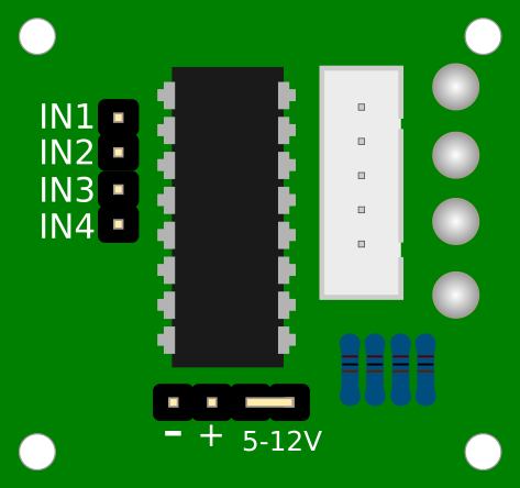
You need 12 male-female jumpers to connect each driver pin to one of the rows of the breadboard with the arduino. Watch picture and just follow the table!
| Left Driver | Arduino | Right Driver | Arduino |
|---|---|---|---|
| IN1 | D9 | IN1 | D5 |
| IN2 | D8 | IN2 | D4 |
| IN3 | D7 | IN3 | D3 |
| IN4 | D6 | IN4 | D2 |
| - | GND | - | GND |
| + | VIN | + | VIN |
Plug keypad
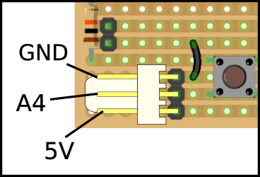
We showed you before, if you're using a two-wire keypad (default), you just need to connect the upper pin with GND on the Arduino and the middle pin to A4. If you're using a three-wire keypad (custom geeky configuration) you also have to connect the bottom pin to 5V. Watch picture!
Plug buzzer
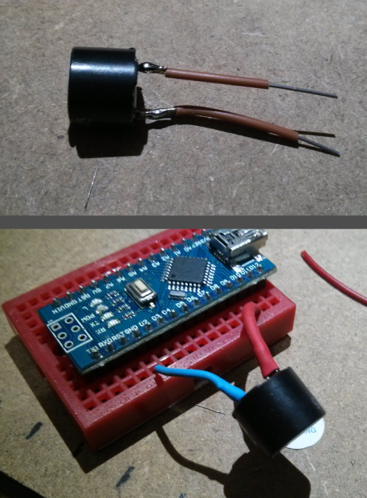
Unfortunately, if you're using an Arduino Nano, the buzzer is not going to fit properly on the breadboard. Of course, you are thinking that we are not very good designers. You are right, but, of course, we've got an excuse! (1).
Anyway, it's not very elegant, but we've got a workaround. You have to solder to pieces of solid core wire on both legs of the buzzer, then plug the long leg, also labeled "+" to the D10 pin and the short leg to GND. We hope you see what we mean with this two beautiful pictures!
Feed it!
Now, we need to supply our escornabot the energy it deserves... so take the red wire that comes from the battery and plug it on the Vin line of the arduino, and take the black wire to GND. It's quite nice to put some kind of male terminal on this wires.
So, you're done with this... you only have to download the code to your computer and upload it to the arduino!
(1) - We started using Arduino Pro Mini, it's a bit smaller than Nano, so the buzzer fit. Pro Mini doesn't have USB connection, so you have to buy an special connector to program it. That is the reason why we switched the default controller to Arduino Nano, although now you have to make this akward operation to connect it.
